gear misalignment
The subject addressed in this article is the misalignment of gears.
Misalignment in gearboxes
A very common way of misalignment of gears occurs in boxes where, over the years of operation, the bearing boxes are gaining slack and, because of this, the gears are misplaced, that is, misaligned. This is reflected in the degradation of gearing and an increase in the level of vibrations., mainly on rotational speed frequencies and gearing frequency harmonics.
Misalignment in open gears
On open gears, the different sprockets are individually mounted on separate frames and are more susceptible to assembly misalignment than box mounted ones.
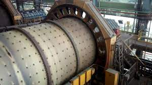
This type of misalignment has specific vibratory symptoms..
example of dgear misalignment – cement raw mill
In the following figure you can see the global levels of vibrations, caused by vibrations at the gearing frequency, the bearings of the drive sprockets (with Spurs), from a raw mill to a cement plant, misaligned crown.
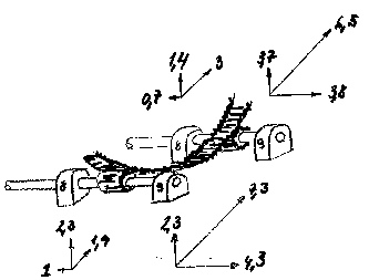
Figure – Vibrations in the bearings of the drive of a driven gear mill with Spurs
note:
- The level asymmetries, between the bearings on the free side and the drive side;
- The high amplitudes in the horizontal and axial direction in the free-side bearings.
From these levels, it can be inferred that the bearings on the free side are more loaded than those on the drive side and that, therefore, the crown gear is misaligned with the pinions.
After correcting the mill shaft misalignment, the vibration levels dropped 40%.
Example – Gearing frequency phase analysis
The phase analysis of the gearing frequency, common vibration analyzer, can serve to determine the mode of vibration of a machine and thus try to draw conclusions about the causes that cause.
In the following figure, you can see the result of the component phase analysis at the gearing frequency (and harmonic), carried out on the bearings of a drive pinion of the crown of a windmill.
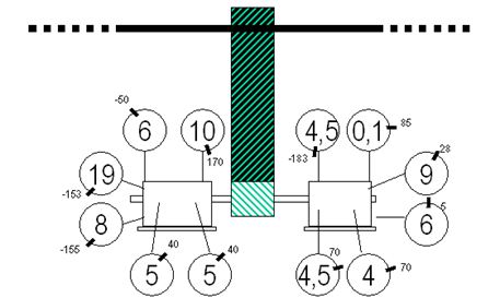
Figure – Phase Analysis allows to conclude that the movement
of the bearings is as seen
a) Movement in the vertical direction

b) Movement in the axial direction
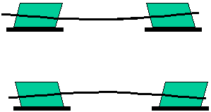
Fig. – Relative movement of the bearings as can be concluded from the Phase Analysis
From these movements it can be concluded that the relative position of the bearings was the one seen in the following figure..

Figures- misaligned bearings

