Vibration Analysis turbine combined cycle
For proper Vibration Analysis in combined cycle turbine, it is necessary to take into account behavioral changes and not just be guided through some alarm levels, because as we can see in the real case of a combined cycle turbine, given below, amplitude levels are within acceptable limits.
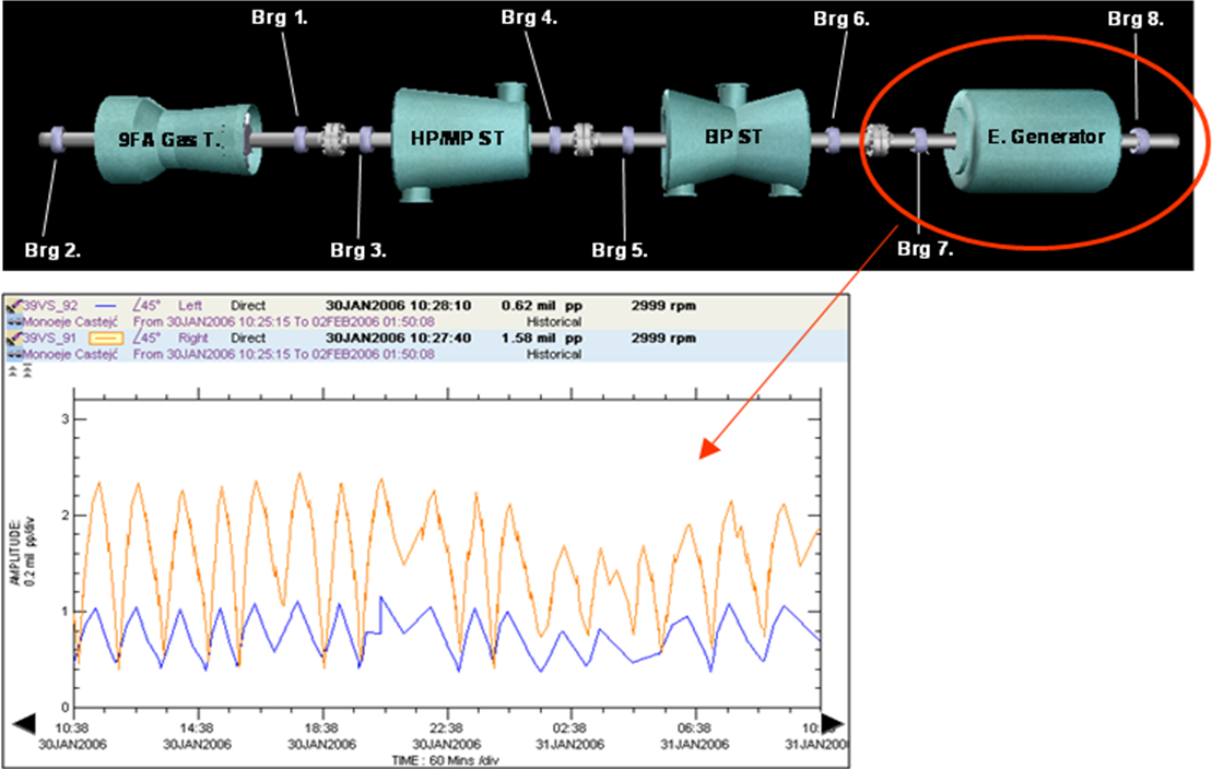
Figure 1 Scheme level of vibration and oscillation in the bearing 7
Reviewing the vibration trend, it can be observed, especially in rolling 7 generator, the vibration amplitude ranges from 0,5 e 2,5 mils (Figure 1), although this variation is appreciable throughout the undercarriage (Alarm Level 6,5 mils.).
vibration changes occur mainly in component 1X to 50Hz, altering both the amplitude and the phase (Figure 2), which is a clear symptom of friction near the bearing 7.
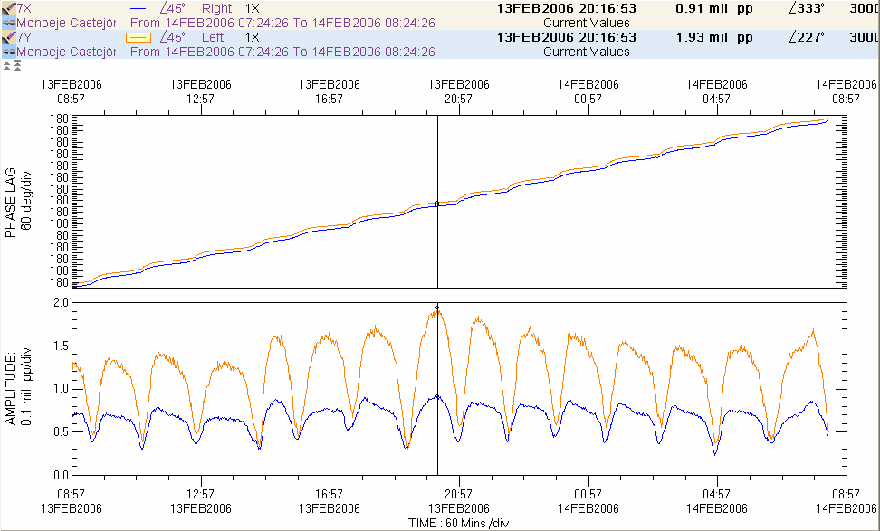
Figure 2 Oscillation amplitude phase the bearing number 7
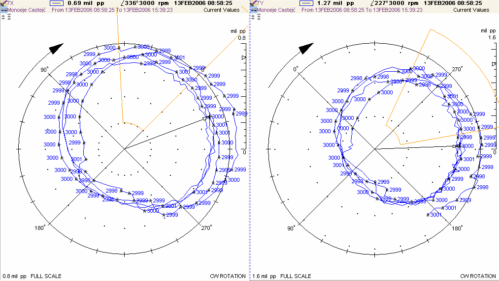
Figure 3 phase amplitude oscillation on the bearing number 7, polar diagram shown in
Vibration analysis in combined cycle turbine - information analysis and actions taken
The operation team and plant maintenance reports that a new set of rotor grounding brushes was installed. To follow, you can see a diagram and photo of rotor grounding brushes and its support.
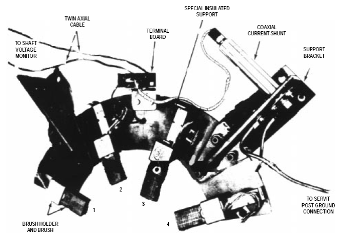
Figure 4 Arrangement of the bearing brushes 7
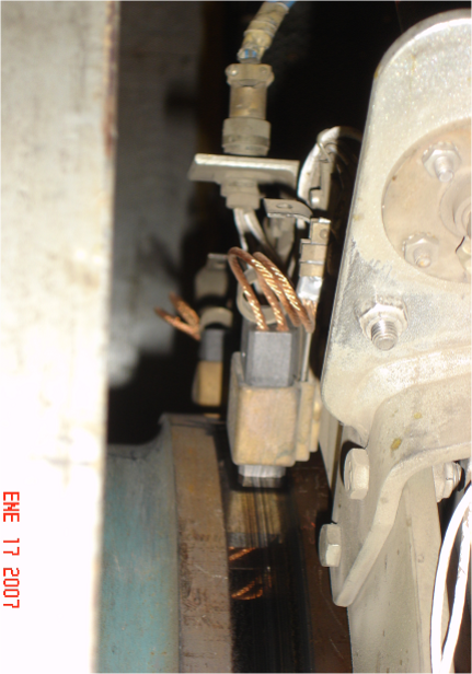
Figure 5 – Vibration Analysis turbine combined cycle - mounting the bearing photograph of brushes 7
Due to high levels of vibration of the brush holder, measured with a vibration analyzer, and a considerable temperature increase, decides to reassemble the original set according to the manufacturer's recommendations.
Set aside the brushes caused friction, it appears that the reference supplied by the manufacturer is mistaken, It is of greater hardness than the recommended.
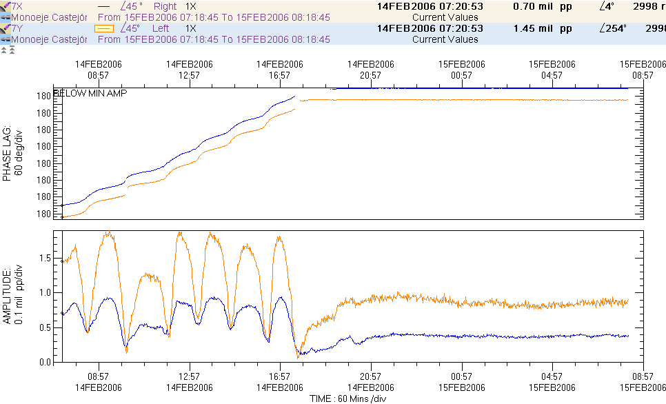
Figure 6 – Vibration analysis combined cycle turbine - the evolution of the vibrations after replacement of the brushes
Friction definitely disappeared while riding the original brushes, as shown in Figure 6.
Lesson learned: you need to check all spare parts immediately after receiving them. In this case, the error was a reference product change, giving the manufacturer more stiff brushes than recommended.
authors:
Gomez Gustavo Doncel
- ENGINEER T. INDUSTRIAL MECHANIC
- Polytechnic University L.A., Zaragoza
- ISO 18436-2 VBRATION ANALYST – CAT. III
- National responsible for predictive maintenance vibration and partial discharges for IBERDROLA (Grade)
Andrés Montemayor
- MECHANICAL ENGINEER
- National Autonomous University of Mexico
- ISO 18436-2 VBRATION ANALYST – CAT. III
- International responsible for predictive maintenance vibration IBERDROLA (Grade)


