Analysis of imbalance vibrations
1 – Unbalance vibration analysis – Introduction
A Vibration Analysis the imbalance of a machine is an important preliminary to the next step, which is the balancing of its rotor. This action can be carried out in the form of equilibragem no local, common vibration analyzer, or in bank. Rotor imbalance is one of the most common defects that generate excessive vibrations in machines.. Therefore, anyone who wants to understand the dynamic behavior of equipment in operation must have a reasonably complete understanding of this phenomenon.. This is essential to successfully implement a program of predictive maintenance.
The following is an overview of the different aspects related to this anomaly..
2 – Imbalance and frequency spectrum
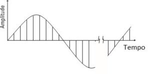
Perhaps the first fact that anyone who approaches the interpretation of the Frequency Spectrum becomes aware of is that the imbalance manifests itself in the Spectrum in the form of a component to the rotational speed as can be seen in Figure 1.
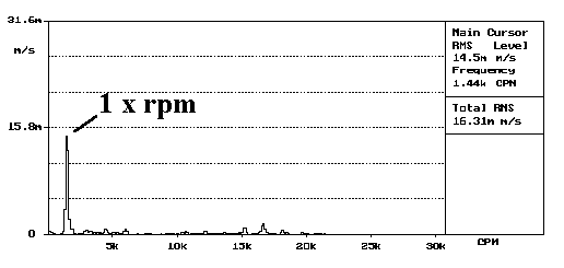
Figure 1 – The imbalance manifests itself in the spectrum in the form of a component raised to the frequency of the rotational speed., in the analysis of imbalance vibrations.
This fact is easily understandable if one considers that an unbalanced mass generates a centrifugal force during machine operation..

3 – Types of imbalance and form of vibration
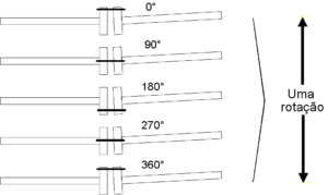
According to ISO 21940 there are basically Static Imbalance and Momentum Imbalance that can combine to generate a Dynamic Imbalance, as can be seen in Figure 3.
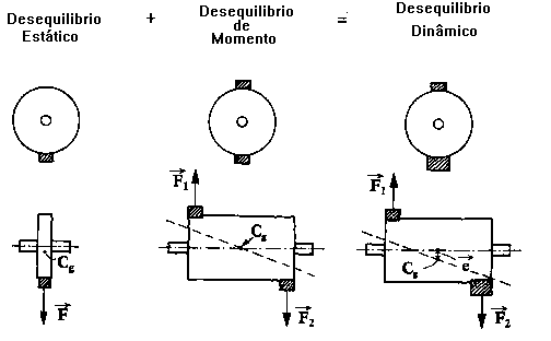
In phase in case of a static imbalance, and in phase opposition in the case of a moment imbalance. In the case of dynamic imbalance, they will have an intermediate movement.
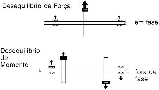
Next, the effect of the type of imbalance on the phase of the vibrations can be seen..
Another relevant factor in the way the machine vibrates is the rigidity of its bearings.. Naturally, the machine will vibrate more in the direction where it is less rigid..
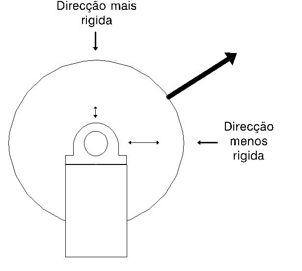
It is for this reason that most horizontal shaft machines vibrate more in this direction.. Indeed, in machines with this arrangement the bearings are normally less rigid horizontally.
Another factor that must also be taken into account is the symmetry or asymmetry of the rotor.. In the case of a symmetrical rotor, the generated centrifugal force will be equally distributed among the bearings., owing, therefore, there is a symmetry of vibrations, while in the case of an asymmetrical rotor the bearing more loaded by the imbalance must vibrate more.
Consider for example the results of measurements of the Global Level of Vibrations, carried out with a vibration meter on a pump with unbalanced coupling.

It should be noted that the vibrations are greater in the bearings on both sides of the coupling due to the fact that the bearings most heavily loaded by the imbalance are located there.
It should also be noted that the vibrations are greater in the horizontal direction, as this is the direction in which the bearings have less rigidity..
4 – The vibrations in the axial direction
A particular behavior is that of cantilevered rotors. An imbalance in this type of rotors generates axial vibrations.
The following table shows the vibration levels before and after balancing a cantilever rotor. (.mm/s RMS)
Table – Vibration levels before and after balancing a cantilever rotor
(mm/s RMS)

Note the high levels of initial vibrations in the axial direction that disappear, parallel to what happens in the radial directions, after balancing.
Below you can see a demonstration of the effect of an imbalance, on the axial vibrations of a cantilevered rotor.
5 – Vibration analysis of imbalance and phase of vibrations
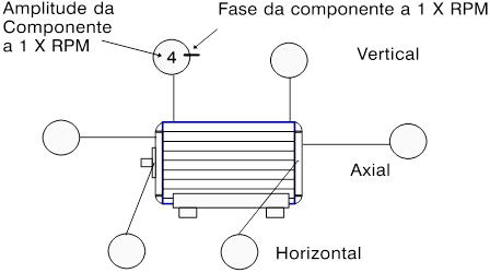
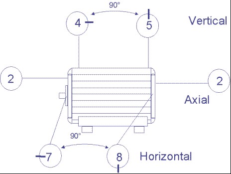
When measuring the phase of vibrations (more properly the phase of the component at the rotational speed) there is a convention that allows to gather in a single schema all the information (1). Within the circles shown in Figure 10 the number represents the amplitude of the component at the rotational speed. The dash in the circle represents your phase, originating at the top point of the circle and counting clockwise. For each measurement point there is a circle with information regarding the amplitude and phase of vibrations..
With regard to the phase, a symptom of imbalance is the difference in phase between two measurement points in one direction being equal to the difference in the other. Indeed, if an imbalance is imagined as a moment rotating inside the machine, it is understandable that differences in phase, between measurements taken, in the same direction, on two bearings of one machine, are the same regardless of the direction in which the measurements are taken.
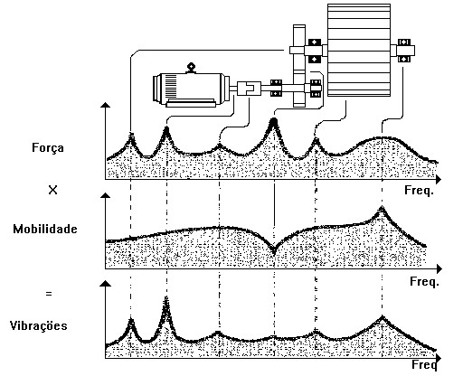
This is not always the case due to the mobility of the bearings (ratio between the response of a structure and the force that excites it) influence not only the amplitude of the vibrations (especially in resonances) as well as the phase, and be different in different directions.
The fact that mobility influences the phase prevents the immediate knowledge of the position of the unbalanced mass when it is measured..
6 – Vibration analysis of imbalance and repeatability of measurements
Repeatability of measurements
If there is no repeatability in amplitude and phase in the measurements carried out between consecutive starts of a machine, without there being no obvious cause for it, it is natural that there are masses in the rotor that assume different positions from start to start. This is usually due to loose masses. Under these conditions, balancing cannot be carried out..
hot imbalance
A more frequent case occurs with rotors running hot.. When cold they are properly balanced and, therefore, do not generate vibrations; when hot they warp an eccentricity of the mass arises and an imbalance is generated.
Imbalance due to incorrect start-up
On large machines (Megawatts) with temperature stabilization thresholds during start-up, the final disequilibrium condition, with the machine running, may depend on the boot procedure followed. As the procedure is more or less adequate, the machine will have more or less vibrations in operation., depending on whether the rotor end warpage is greater or lesser.
7 – Some easy mistakes to make
When balancing a rotor, there are two errors that can occur to the least aware:
– Not taking into account the braces
– In the case of rotors balanced by parts, do not be careful with mounting tolerances
To Key
If no precautions are taken when balancing a shaft, this is carried out without the groove where the key will be placed being filled. When the key is mounted on the shaft, it may cause an imbalance out of tolerances.
At ISO 21940 contain conventions on this aspect. In particular, it gives some suggestions for making half keys to accompany the shaft in balancing.
Mounting Tolerances
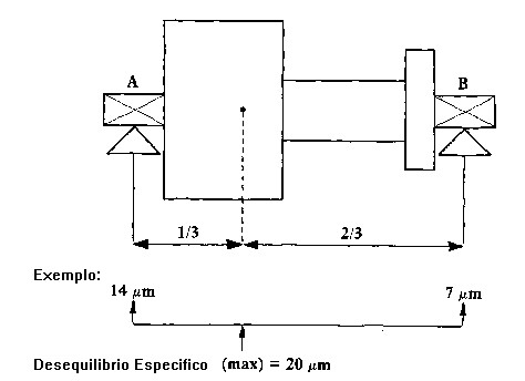
On the abacus below, withdrawn from ISO 21940-3, you can see the balancing tolerances as a function of the machine's rotational speed and the Balancing Class. This tolerance is expressed in g.mm/Kg or μ. This distance expressed in microns represents the distance between the axis of rotation and the axis of inertia..
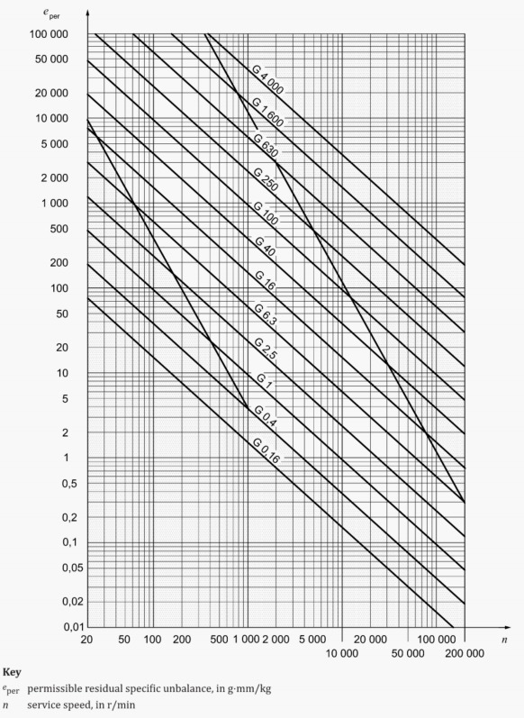
Take, for example, the case of a rotor rotating at 3000 RPM, to be balanced to the Degree 6.3. The balancing tolerance is 20μ. From this it can be immediately concluded that an assembly that does not respect this tolerance will degrade the balancing quality of a rotor., for values outside the tolerances.
Hence the rule of, whenever possible, the rotors are fully balanced.
If this is not effectively possible, it is necessary to play with the position of residual imbalances of the different parties., and ride them against each other. Extreme care must also be taken with the mounting clearances between the various parts..
8 – flexible rotors
Rotors operating above their first natural frequency deform and behave in a so-called flexible behavior..

A rotor operating under these conditions must be balanced to its rotational speed., Unlike rigid rotors (rotor operating below its first natural frequency), which are actually the most common.
9 – summary of symptoms in imbalance vibration analysis
Below is a table with a summary of the main symptoms of imbalance..
| Spectrum Frequency | Large component at rotational speed |
| predominant direction | Radials. Also axial on cantilevered rotors |
| Direction – relative proportion | Greater in the direction of greater flexibility |
| Phase | Difference in one direction equal to the other |
| Local | Bearing more loaded by imbalance |
References
1 – Practical Solutions to Machinery and Maintenance Vibration Problems – UPDATE International Inc.
2 – ISO 21940 – Mechanical vibration – Rotor balancing

