Alignment shafts
Improper alignment shafts, also known as misalignment, It is a mechanical defect, which is defined as the lack of spatial coincidence of the geometric center of rotation of two coupled drive shafts (shafts). Improper alignment concept is also definable for other types of transmission (pulleys, cardan, etc.) such as lack of coplanarity between the geometric centers. Finally, the same concept is applicable to characterize the relative position of a shaft relative to its supporting elements (bearings or bearings).
The DMC provides alignment service shafts.
Effects of Misalignment shafts
Improper alignment shafts, so common in industrial process equipment, He produced and continues to produce great economic losses in terms of cost of spare parts (engagements, bearings, mechanical seals, etc.), skilled labor and production stop. Consequently, the alignment of shafts is an important technical aspect of the project equipment and the implementation of construction, installation and maintenance that affects the mechanical charge, supervisors, engineers and even plant management.
According to studies published in the Journal TAPPI in December 1990, the inclusion of a compliance program precision shafts within the maintenance plan may involve:
- An increase in bearing life up 8 times;
- Absolute reduction in maintenance costs of up to 7%;
- An increase in the availability of up to machines 12%;
- A reduction in downtime due to misalignment of up to 50%;
- Savings of 5% energy consumption.
Although mounted couplings are flexible and have self-aligning bearings, the life of the mechanical elements in high-speed machines (RPM) It depends directly on the correct alignment of its transmission.
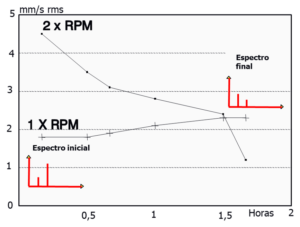
Improper alignment shafts, Excessive vibrations frequently yields readily identifiable by Vibration Analysis.
Misalignment causes the shafts
For many years, the responsibility for implementing the alignment of the shaft fell on specialized workshops, having inadequate tools often used to measure the misalignment, and correcting the machine position.
Often, much attention is given to the alignment of shafts of critical equipment and high power machines, completely forgetting that other less relevant units, cause costly downtime, due to premature deterioration of the bearing itself and the coupling.
Among the factors contributing to misalign the shafts of the machines engaged in operation we can mention the following:
- Design of equipment with low stiffness materials that deform in operation when transmitting all its power.
- Construction of mechanical elements out of tolerance specification.
- Mount defective or inadequate foundations, where the geotechnical strength can cause the veins to move in a certain direction.
- Chassis without stiffness, cracked by dynamic fatigue, generously sized mooring bolts, with inadequate grip or uneven seats (false legs).
- Dilation of thermal origin due to differences in operating temperature caused by heat generated in the bearing and transmitted to housing, the surrounding fluid (lubricants, refrigerants and other process fluids), etc.
All of these factors or operating conditions “hot”, They must be taken into account when performing an alignment of shafts with the equipment “frio”. Oftentimes, the alignment specifications “frio”, provided by the equipment manufacturer, do not apply to the actual installation situation, as it differs considerably from the manufacturer's design parameters (room temperature, type base, location pipes, providing auxiliary equipment, lubrication system, etc.).
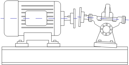
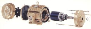
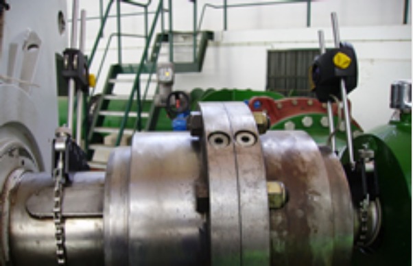
Figure 1- Alignment shafts – pump with direct coupling misaligned due to misalignment of shafts whose effects are easily identifiable with a vibration analyzer
Types Misalignment shafts
It can be said that there are two basic types of misalignment shafts:
- Improper alignment parallel shafts (also called offset) e
- Angular Misalignment shafts,
as illustrated in the following figure.
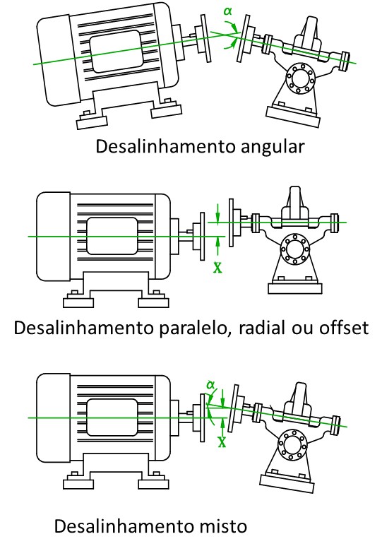
Figure 2 – Alignment shafts – types of misalignment shafts
However, a mechanical problem shafts misalignment usually appears as a combination of these two basic types, which makes the geometric approach measurement, a three-dimensional problem, which is more complex to solve.
measuring Misalignment shafts
The angular offset of the measurement units can be degrees (sexagesimais) ou miliradianos, while, for measuring the radial misalignment, are used microns or millimeters. Although this seems simple and reasonable, in practice there may be a lot of confusion if the existing type of misalignment has not been set correctly.
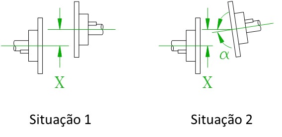
Figure 3. Alignment shafts – different measures of misalignment shafts
In the previous figure, are represented two shafts misalignment situations. The first is the parallel type (offset), while the latter is mixed (combined) offset-angular. At first sight, the value X is identical in both cases, in the second case but the measurement value would be further characterized by angle α. With regard to the dynamic behavior from the standpoint of mechanical vibrations, the first situation is, a priori, mechanically more unfavorable than the second and manifest a higher vibrational severity.
Units in which is expressed the improper alignment of shafts
Some coupling manufacturers specify their products to an allowable maximum angular misalignment (I degrees) e offset (in millimeters), although, sometimes, a maximum value in millimeters is specified only for a mixed displacement and angular misalignment. One should take care that the coupling supplier specify the assembly tolerances separately, beyond the power characteristics, rotation and transmitted torque and maintenance requirements. Though some flexible couplings admit significant angular misalignment, often occurs such that a set operating conditions, It does not produce coupling destruction, but quickly degrades bearings working with inadequate fatigue loads.
In this article, the offset values are expressed in terms of parallelism (offset) and always refer to the two transmission points in each coupling plane, as illustrated in the following figure.
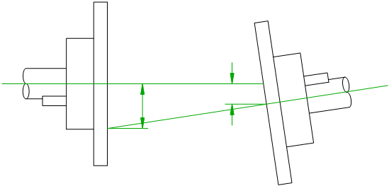
Figure 4 Alignment shafts – measuring misalignment in coupling
tolerances Misalignment shafts
A very important fact to perform alignment work is to record all measurements before and after work. This information can be very useful for the realization of future realignments.
Normally, the equipment manufacturer to align must specify the allowable values of misalignment tolerance, combined and expressed as angle compensation, or as a maximum compensation in each coupling plane. The alignment tolerances may be related to the position of the shafts during assembly of the coupling or cold to normal work equipment. In any case, it may happen that the equipment tolerance specification is not the most suitable for the operating conditions of the current installation, which can vary substantially project, in which case you need to make a study (geometric, thermal, etc.) the ideal position of the shafts.
general recommendation alignment tolerances
In some equipment, whose manufacturers do not specify the alignment conditions or those whose design tolerances are not in accordance with the actual operating conditions, can apply some guidelines tolerance, as appropriate. A guide is a graph depicting the permitted values of misalignment as a function of the distance between the coupling flanges. For couplings with coil or higher extension 500 mm. in length, They can be taken into consideration tables of tolerance that does not include the concept “offset”, but in standard couplings case it will be essential to include both concepts “Offset angle” besides the rotation speed in RPM.
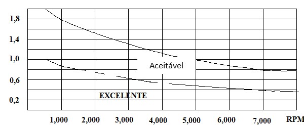
Figure 5. Alignment shafts – guide angular tolerances (mrad) in dentate couplings
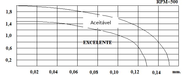
Figure 6 Alignment shafts – guide angular tolerances (mrad) e offset (mm) for RPM <500 in normal couplings.
Logically, alignment must be precise in transmissions working at high speed, as a fast machine always transfers great power. A manufacturer of laser systems for alignment recommends applying the following classes of tolerance for standard couplings and extension.
Table 1. Alignment tolerances for long engagements with reel
|
Offset |
Angular |
Offset |
Angular | |
|
0 < RPM < 500 |
0,13 mm. |
1,50 mrad. |
0,15 mm. |
2,00 mrad. |
|
500 < RPM < 1,250 |
0,10 mm. |
1,00 mrad. |
0,13 mm. |
1,50 mrad. |
|
1,250 < RPM < 2,000 |
0,08 mm. |
0,50 mrad. |
0,10 mm. |
1,00 mrad. |
|
2,000 < RPM < 3,500 |
0,05 mm. |
0,30 mrad. |
0,08 mm. |
0,50 mrad. |
|
3,500 < RPM < 7,000 |
0,03 mm. |
0,25 mrad. |
0,05 mm. |
0,30 mrad. |
|
7,000 < RPM |
0,01 mm. |
0,20 mrad. |
0,03 mm. |
0,25 mrad. |
General procedure for aligning shafts
Depending on the mechanical state of the equipment and the knowledge and skill of the operator who makes the alignment shafts, an alignment can be a simple dimensional check, a fix that can be done in a few hours or an extremely delicate task that can take up to a week. In short, the following complete procedure, comprising the steps of:
- Dynamic check before the machine stops.
- Preliminary checks the radial and axial clearance, paw thigh and cleaning.
- Installation of measuring elements (comparators, lasers).
- First reading deviations and verification tolerances.
- analytical calculations, graphic or numeric applicable vertical corrections.
- Calculation of thermal expansion in operation.
- vertical leveling movement with shims.
- Second reading to check the vertical correction and calculate the correction movements in the horizontal plane.
- Correction with horizontal adjustment screws.
- Third reading to verify the tolerances in the vertical and horizontal.
- Equipment start-up and dynamic check vibrations in operation.
Requirements for alignment work
It is very important to have everything you need before you start working, because the unexpected involves a huge waste of time. It is advisable to remember the following:
- Having easy access to the machine.
- Have the power to maneuver, start and stop at will.
- There are means for rotating the shafts progressively.
- There are all the necessary tools: dimensional measuring elements, thermometer (contact or IR), cloth tape to eliminate backlash, jack for controlling the axial and radial, suitable tools and meters to fit the legs of the machines
- Overseeing the safety at all times.
I Preliminary observations before the shaft alignment work
Previously, detailed to the general procedure for the measurement and shaft misalignment correction, underlined the need to provide all that is needed before starting work. As a first analysis of the initial situation, It is interesting to note the possible uneven settlement of the feet of the machines (paw thigh), the existence of radial and axial clearances of the shafts and a first coarse measurement of the misalignment of the shafts.
Checking the irregular settlement of the feet of the machines (paw thigh)
A situation paw thigh on a machine, It occurs when the seats of all the legs of the machine does not come into contact with the base at the same time, during assembly. It is the same situation that occurs on a table with your feet not level, except for the fact that, if the machine fastening screws are tightened, a structural deformation is forced in the coating or in the machine casing, which will eventually result in misalignment of bearings and a faulty operating condition.
Logically, a machine that is not settled evenly on the supports of the base undergoes an elastic deformation upon tightening the bolts. When these screws are loosened to move and support the machine, the situation of “freedom” the machine is retrieved, It is absolutely impossible to perform a reliable measurement of misalignment of the shaft. In short, it is essential to eliminate the condition of thigh leg before proceeding to the measurement and correction of the position of the shafts.
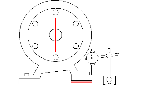
Figure 7. Alignment shafts – irregular settlement detection “paw thigh”
thigh leg locating procedure
- Check whether all the machine clamping screws are tightened. If no, proceed to the immediate tightening them.
- Place an indicator / comparator in the paw to be checked, as shown in Figure, with enough room to maneuver the tool and loosen the fixing screw, little by little.
- If the comparator detects a greater vertical displacement 50 microns, it can be stated that said leg is incorrectly seated in the base. If this is not the case, the same operation must be repeated on all machine feet.
- Once located one or more legs thighs, they will be equipped with wedges, preferably made of stainless steel. The following figure illustrates different types leg paw.
- Once all the legs have been adjusted and the uniform position of all of them has been verified on the basis, the position of the shaft can be measured and corrected.
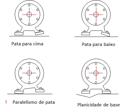
Figure .8. Alignment shafts – different types of irregular settlement “paw thigh”
axial clearance, torsional e radial
To determine the position of the shafts, it is necessary to know in advance whether there is slack in the radial direction and / or axial. If there are gaps, the actual position of each shaft in operation should be estimated to correct the measures taken in relation to the actual situation of operation.
On machines with flat thrust bearings, the existence of an axial clearance is normal. This factor is not very relevant and little affects the measurement accuracy, although it can be neutralized with the aid of a hydraulic jack during the measurement of misalignment of shafts.
Some couplings may have a certain torsional backlash. He, when carrying out measures, The technique requires that the two coupling flanges rotate together, It can neutralize the backlash with fabric resistant tape, firmly holding flanges. In the specific case of laser measurement systems, the neutralization of the torsional backlash is vital for good measure deviations. In any case, it is recommended to rotate the shafts in the same direction to avoid problems of torsional backlash.
Finally, the radial clearance is greater that difficulty can cause. First of all, It is essential to know the origin of radial clearance, for if it is due to poor mechanical condition of the bearings support, the first thing to do will be to repair.
Deformation and irregularities of the shafts “Runout”
Before starting to take measurements of the deviations, It is essential to make a visual inspection of the wear condition of the different coupling elements. For example, is very important to verify that the key is fully inserted and if there are no gaps in the assembly of the coupling flanges in their respective shafts.
Another possible problem that should be known before alignment, It is called “runout”. We can define as “runout” (deviation of circularity) any defect in the set of geometric shaft flange, so that there is a deviation of the axis. This deviation can be attributed to a permanent deformation of the shaft (He came warped), lack of collinearity between the shaft and the housing flange or the coupling between them a parallel.
To assess the “runout” an assembly, comparison place the probe on the periphery of coupling flanges, rotating a full turn and noting values of the maximum deviation. It is also convenient to take the deviation Note on the shaft, the coupling hub and neighborhood to determine what type of problem must be corrected.
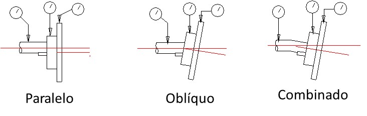
Figure 9. Alignment shafts – different types of “Runout”
Strain induced pipes
The deformation induced by pipes (With, oil, Water, …) connections to the machines can produce a similar effect to the “paw thigh”. To find this kind of problem, the comparator can be arranged palpating the coupling in the vertical and horizontal directions. When the fastening bolts are loosened legs machine, any variation greater than 40-50 microns in windows, may indicate a problem of this type, that would force the release of the flanges of all the pipes to align correctly. In some cases, the effect of appropriate expansion joints tubes can be alleviated.
rough measure Misalignment of the shafts
Sometimes, alignment work is carried out with rudimentary means and without any dimensional accuracy. Such is the case of the use of rules, saw blades, etc., for positioning references Shaft. Other methods employ stricter thickness gauges or internal micrometers to verify the relative position of the coupling flanges. In either case, all of these methods are only approximate measures of misalignment that can be used to get an idea of the positioning of the shafts, but never to calculate and correct the positions of the same, with accuracy.
For the correct measurement of the misalignment of shafts, no minimum, They will have to be used comparators micrometric precision. There are measuring systems by comparison, with the correction of the deflection of the bars (sag) assembly and laser systems, that ensure accuracy in much greater measurement and correction.
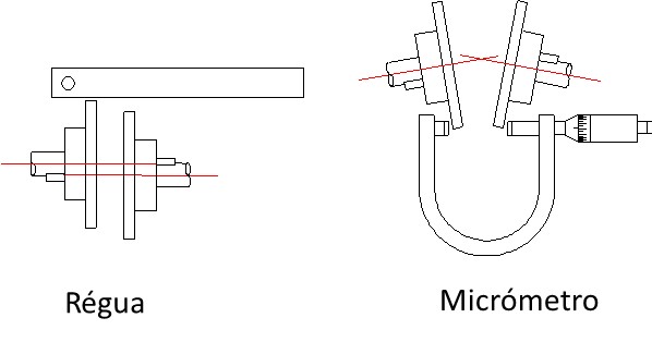
Figure 10 Alignment shafts – approximate measure of the misalignment of shafts
II-face alignment with the periphery method
A very common method used is the alignment measurement of the positional deviations of the shafts of the machines, micrometric comparator. These instruments usually have excellent accuracy and can be reset (“reset”) make yourself comfortable, making it easy to obtain references in measurements. Regardless of the comparators used are entirely mechanical or digital electronic, measurement techniques are commonly used two: measuring in face-periphery and measure and measure the two opposite peripheries.
The traditional method of alignment with side-edge comparators is illustrated in the following figure. This method consists in measuring the radial and axial deviations, usually with the uncoupled shafts (open coupling), although it may also be applied in closed engagements, with a suitable tool. For this purpose, a bolted flange fixing, which supports the two comparators, It is mounted on the shaft of the movable machine. The probes of the comparators will be in contact with the cylindrical periphery and the flat face opposite the flange, sequentially recording the readings at positions 0 ° / 90 ° / 180 ° / 270 °. Note that the flat face probe should be as close as possible to the periphery, so that its maximum turning diameter is obtained and to achieve a higher accuracy.
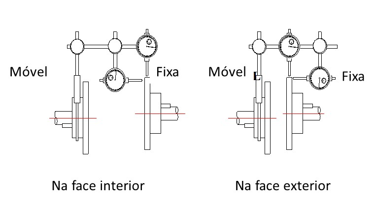
Figure 11. Alignment shafts – measuring deviations from the face and the periphery
Advantages of the method of thelinhamento the face-edge method
The fundamental advantages of this method of measuring, shifts are the following:
- • Only one of the two coupling shafts must be rotated.
- • It is a very simple method when it comes to large diameter couplings with flanges very close to each other.
- • The position of the shaft is achieved in a very intuitive way.
- However, this system also has drawbacks:
- • In assemblies with flat thrust bearings, the measures on the flat face lack precision due to the slack in that direction.
- •Oftentimes, It is necessary to remove the coupling to make measurements of deviations in flat face.