ACMT to ADASH
This article explains what ADASH's ACMT signal analysis technology consists of (Adash Compressed Measurement Time).
De facto, when it takes place vibration analysis , in a vibration analyzer when performing predictive maintenance, common vibration analyzer This article presents the vibration limits in rotary-dynamic pumps as defined in the ISO series of standards..
Vibrations generated by short-term impacts
It is known that there are several faults that produce short-duration pulses in low rotational speed machines.. Pulses are often caused by bearing defects, gear box wear, etc. It is important to be able to accurately detect and analyze these impulses., in order to make a correct diagnosis.. It has to be taken into account that each individual impulse can have a very short duration..
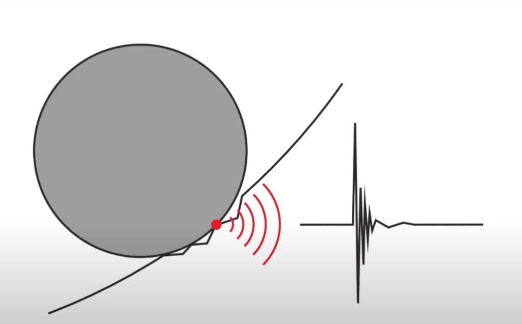
When impact occurs, the structure is, for a very short time, to vibrate at its natural frequency.
On the other hand, on low speed machines the interval between pulses can be quite long.
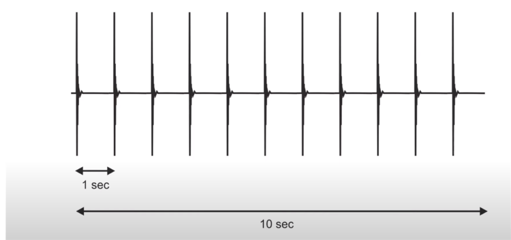
The duration of short-term impacts
Impacts excite the natural frequencies of machine elements (bearing races, gears, etc.) which can be quite high, typically 5 e 20 KHz.
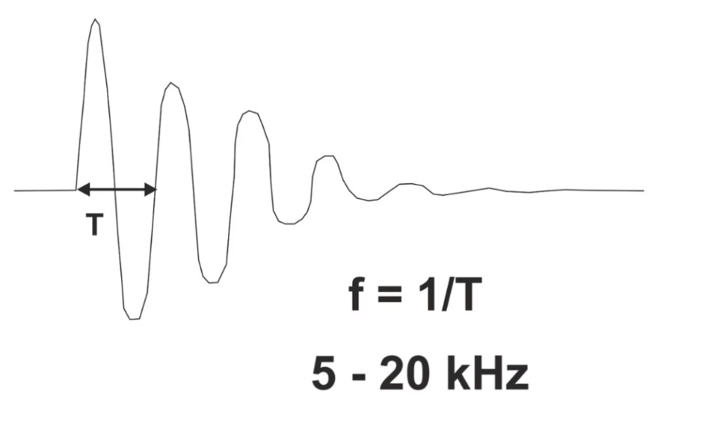
For example, a natural frequency of 5KHz corresponds to an oscillation period of 0,2 ms.
And this is the order of magnitude of the duration of impacts.
Correct measurement of the amplitude of vibrations resulting from short-term impacts
First let's remember that the sampling frequency of the waveform is normally equal to 2,56 times the maximum frequency of the spectrum.
For example:
- If we want to see a spectrum of a bearing with damage up to 1000Hz the sampling frequency of the waveform will be 2560Hz. That is, between two samples decorate 1s/2560= 0.00039s= 0.4ms
- If the duration of the impulse resulting from the shock is less than 0.4ms we will not be able to measure its level correctly…. And this parameter is one of the main indicators of the severity of the damage…
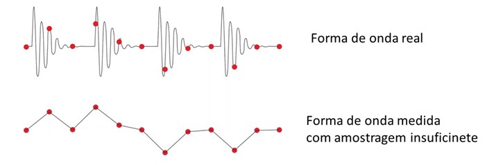
- If we ask for a spectrum with 1600 lines (ate 1000 Hz) the duration of waveform acquisition will be the inverse of the resolution (1000/1600) , ie 1/0.625= 1,6 s;
- If the bearing has a low rotational speed, an impact will occur during this measurement period.?
This introduces a conditionality;
- If we want to correctly measure the level of short duration pulses we have to measure with a very high sampling frequency of the waveform., typically on the order of many KHz.
- If we want to see a spectrum, for example, up until 100 Hz, the sampling frequency of the waveform will be 256 Hz (of 4 in 4 ms we have a sample), that is, normally too low to correctly measure the level of impact peaks.
In other words:
- Consequently, on the one hand, it is necessary to define a high sampling frequency of the waveform to perform the measurement. This is the only way to ensure a correct measurement of the amplitude of the impact peaks..
- On the other hand, the time interval between the impulses generated by the fault can be very long when the machine speed is low (seconds, minutes). That way, to perform a correct evaluation of the signal, it is necessary to capture and observe the time signal that contains, no minimum, various impulses. Thus, it is necessary that the measured signal has a long duration.. For this to happen, traditionally, it is necessary to use a low sampling frequency of the waveform.
That is, these two aspects produce a conflict in the parameterization of the measurement.
What does the ADASH ACMT consist of?
- In order to overcome this dilemma, ADASH ACMT provides a signal analysis technology that solves this contradiction.. This method implements both contradictory requests through two consecutive data samples..
- First, high frequency sampling is performed. (90 KHz for example on VA5Pro) to correctly detect the level of impact peaks.
- Then, data is compressed and resampled with impact peak level retention, according to user defined maximum spectrum frequency requirement.
That's why with ACMT, one can capture a signal in long duration time for evaluation of multiple events and, simultaneously, measure the correct amplitude of impact peaks generated by defects in low rotational speed bearings. (or gears, or others…)
Traditional measurement example
All measurements were made on a low speed 23132-TOR bearing rotating 60 rpm (1 Hz). Bearing has a defect in the outer race. Short duration pulses are generated during operation.
We measure the signal with a waveform of 4 seconds. when they are used 2048 samples (sampling frequency= 0,002 s), then the frequency range of the spectrum (0,002/2,56) is 200Hz.
The waveform has no impulse

Next we use a sampling frequency of 19200Hz. But this way we only measure only 42ms of time signal. The time between impulses is 114 ms. We need to be lucky and hit the impulse.

Example of measurement on damaged bearing without ADASH ACMT
Short-duration impulses usually have small amplitude. They are often modulated by the frequency of rotational speed..
If a traditional measurement is used, the result will be as shown in the following figure.
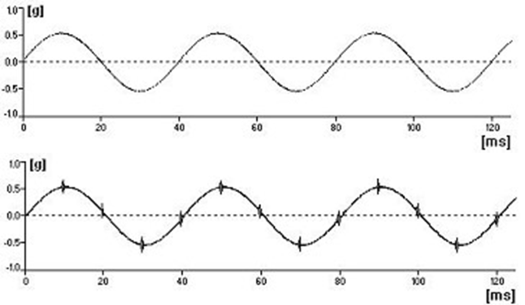
Only the sine wave corresponding to the rotation speed is seen and no or small pulses are seen..
Measurement example on damaged bearing with ADASH ACMT
ADASH's ACMT technique, is used in the next figure. ACMT is used in conjunction with bandpass filtering (as in demodulation) which removes the sine wave corresponding to the rotation speed.
All short pulses are maintained and amplitude modulated for better viewing.

This result is much better, because the scale of the Y axis corresponds to the actual amplitude of the impulses, and not to the amplitude of the sine wave corresponding to the rotation speed.
On the other hand, the long term signal, contains the required number of pulses and the peak level, of each of them, it is well measured.


