Introduction to piezoelectric accelerometers
The topic covered in this article is an introduction to piezoelectric accelerometers.
Introduction
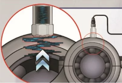
Piezoelectric accelerometers are transducers used for measuring vibrations by measuring vibration acceleration. They can work from a variety of physical effects and are capable of measuring a wide range of acceleration values, logo having a very high range of applications. Piezoelectric accelerometers are widely used in positioning systems, tilt sensors, as well as vibration and shock sensors or connected to Vibration analyzers. In our daily life we are surrounded by accelerometers, applications being well known the orientation of mobile phone screens that adjust according to the angle they make in relation to the acceleration of gravity or the trigger sensors of “air-bags” of cars.
There are numerous types of accelerometers that use different types of physical effects to measure acceleration..
The most used for predictive maintenance in analysis vibrações, are piezoelectric accelerometers and will be discussed here.
Definition of Piezoelectricity
A Piezoelectricity consists of the capacity of some materials (namely crystals and some ceramics) to generate an electrical potential in response to the application of a mechanical force.. This can take the form of an electrical charge in the crystal matrix.. If the material is not short circuited, the electric charge induces a voltage in the material.

Because we use accelerometers piezoelectric?
The reasons why we use piezoelectric accelerometers are as follows.:
- reduced dimension
- light
- with two wires (mares)
- large dynamic range
- wide temperature range
- wide frequency range
- very low noise
- Simple signal conditioning
- economic implementation
Introduction to piezoelectric accelerometers – The Piezoelectric Transducer
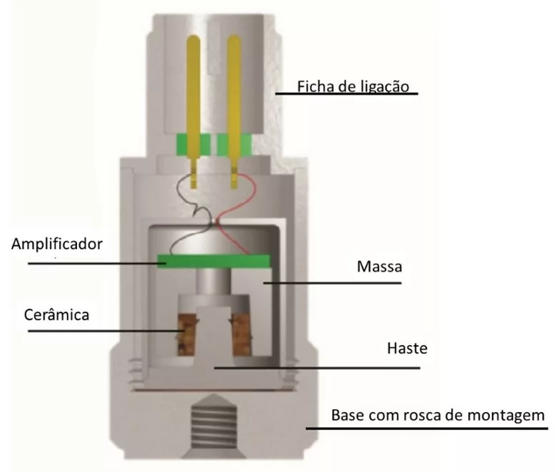
The active element of all piezoelectric devices is a piezoelectric material element. There are many different sensor construction solutions based on different crystals and materials.
The types of piezoelectric sensor conditioning used today are:
- Voltage Mode (with various trade names. mares, LIVM, ICP, Piezotron, Isotron) where there is electronics mounted on the transducer itself;
- Charge mode that are connected to an external charge amplifier
Each has its advantages and disadvantages, which will be discussed below..
Constructive solutions for accelerometers piezoelectrics with integrated electronics (voltage mode)
The main constructive solutions for piezoelectric accelerometers are as follows:
| Characteristic | ||
| Integrated electronics | Yes No need for signal conditioning; more economical. Upper temperature limit imposed by included electronics (Typical example: 120 ºC) Many modern measuring equipment include IEPE power supply. | Cannot withstand higher temperatures |
| Material piezoeltrico | Quartz | Ceramic. more sensitive |
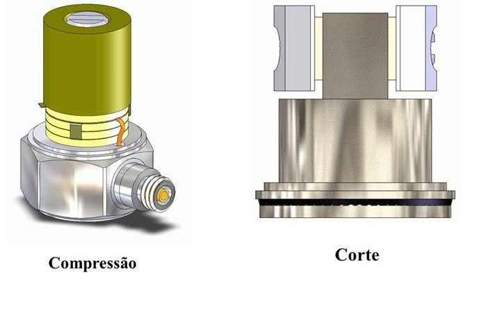
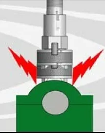
| Piezoelectric sensor assembly | to compression | When cutting Less sensitive to base deformation. |
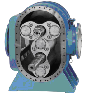
The sensor with piezoelectric material can be mounted by compression or by cutting as shown below. Mounting to the cut has the advantage of being less sensitive to deformations of the accelerometer base.
Input/Output Characteristics piezoeletric accelerometers so voltage (mares)
The following are the main characteristics of piezoeletric accelerometers mares.
Entry: 18 – 24 Volts DC, 2-20mA constant current; input values other than those mentioned may damage the sensor
Exit: voltage proportional to acceleration or vibration
Note: The voltage mode sensor or IEPEE is a two-wire device. (signal/power and ground)
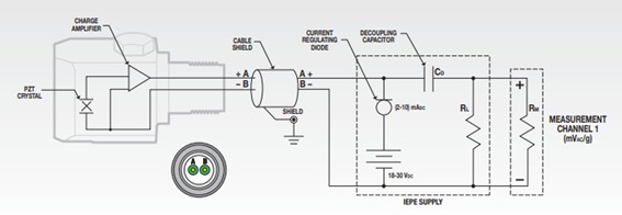
The integrated circuit is powered by a constant current source (see Figure). This constant current source may be part of the instrument or a separate unit. Both the supply current and voltage output are transmitted through the same coaxial cable. A positive bias voltage (Bias Voltage) appears at the sensor output. The vibration signal is transmitted back to the source as a modulated bias voltage. The DC capacitor removes the sensor bias voltage from the instrument input, providing a zero-based AC signal. Since the output impedance of common IEPE-compliant transducers is less than 100 ohms, the cable can be up to several hundred meters long without compromising signal quality. Inexpensive standard coaxial cables can be used instead of expensive low-noise cables.
In the extract from a specification presented below you can see the description of the power supply of a piezoelectric accelerometer.
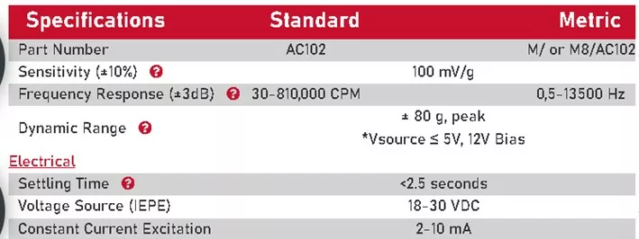
It can be seen that the power supply of this model of accelerometers is between 18 a 30 VDC with a supply current of 2-10 mA.
The Bias Voltage of piezoeletric accelerometers– bias voltage
The bias voltage, that is, the DC output voltage of the sensor with excitation, is normally between 12 e 14 V. It varies with supply current and temperature. The sensor output signal oscillates around this bias voltage. You can never become negative.

Checking the electrical functioning of IEPE piezoelectric accelerometers
When installing a permanent combination of piezoelectric cables and accelerometers, especially in areas that will be inaccessible after installation is complete, It is important to check the correct functioning of the set.
Many accelerometer/cable faults can be diagnosed by measuring the sensor amplifier bias voltage. If the bias voltage is within the correct limits, the sensor and cable will be considered working properly.
Most common accelerometers have a biased output circuit.. Biased output circuits utilize a two-wire sensor system used to measure dynamic AC signals, vibration.
A portable analyzer/external power supply supplies a DC voltage to the accelerometer. The power supply voltage is normally 18 a 30 Volts CC. Sensor amplifier circuit requirements result in voltage reduction to a predefined level. This normally occurs in the range of 10 a 14 Vcc. This is the BIAS voltage that should be measured on the accelerometer in operation.
Some faults of piezoeletric accelerometers have typical symptoms
- A result of 10 a 14 Vcc should be considered a properly functioning accelerometer/cable system.
- The result of a voltage significantly higher than 14 Vcc, What 23 Vcc, an accelerometer/cable system should be considered, indicating poor contact or cable malfunction.
- A result of 0 Vcc will indicate a shorted cable or sensor assembly.
Automatic check of accelerometer operation piezoeletric accelerometers IEPE is an online system
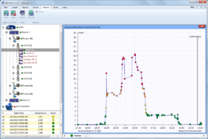
Nowadays, online systems are common, such as the Vibrometer MPS1, have automatic fault detection systems as can be seen in the figure below, where you can see the “Upper OK Level” and “Lower OK level” windows.
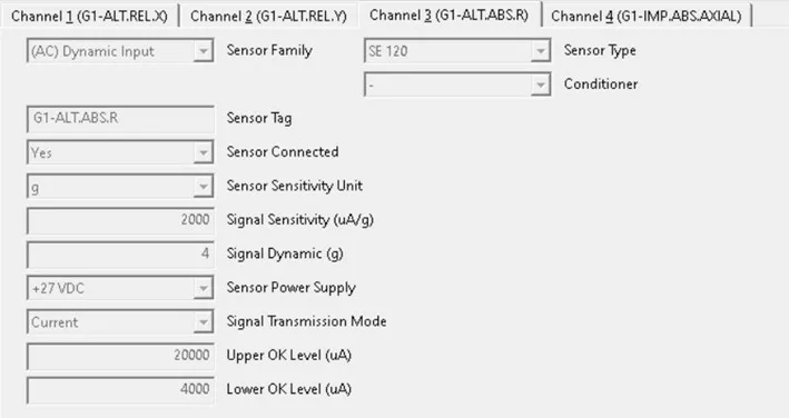
If the electrical signal is not within these values, a sensor/cable failure alarm is generated in the measurement channel..
The feeding of piezoeletric accelerometers in measuring equipment
Modern vibration analyzers are all powered for this type of accelerometer.
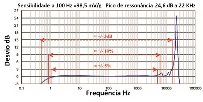
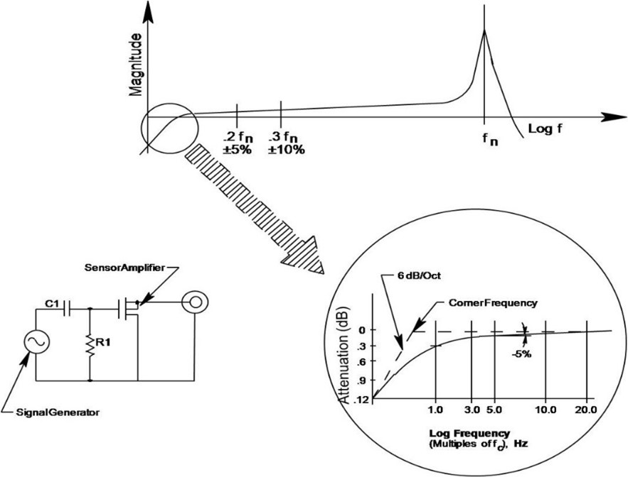
Introduction to piezoelectric accelerometers – Frequency response of IEPE piezoelectric accelerometers
The low frequency response of piezoelectric accelerometers is controlled by the Discharge Time Constant (DTC)
- Factory adjusted and cannot be changed.
- Can be changed at manufacture.
The high frequency response is a function of the resonant frequency (natural) do sensor.
Filters in the sensor or signal conditioning can also affect the sensor's frequency response..
- Highly sensitive sensors typically have a low resonant frequency..
- Low sensitivity sensors typically have a high resonant frequency..
Download Time Constant (DTC)of the piezoeletric accelerometers
Discharge Time Constant - time required for sensor output voltage, to download to 37% of its original value, in response to an abrupt ascent, in step, of input acceleration.
- Determines the low frequency response of the sensor
- The low frequency response is approximately equal to:
Point -3dB = .16/DTC
Point -5% = Point -3dB x 3
Construction solutions for piezoelectric sensors without integrated electronics (charging mode)
The constructive solutions for piezoelectric sensors without integrated electronics are as follows (charging mode).
- They connect to a charge amplifier that converts the accelerometer signal into Volts
- Usually with ceramic sensor
- No electronics included
- Suitable for high temperatures, such as monitoring gas turbines (for example up to 700°C)
- Expensive signal conditioning
- Low noise cables required for most applications
- Load amplifiers are usually more difficult to use (ex.: sensitivity adjustment, etc.)
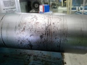
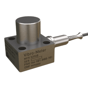
Below you can see the high temperature CA901 accelerometer, that works up to 700ºC..
Introduction to piezoelectric accelerometers – Mounting the accelerometer
How you set up an accelerometer is very important because it can influence its frequency response..
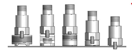
Mounting Types of piezoeletric accelerometers
- Mount with leg
- optimal frequency response
- Adapter glued with epoxy glue, leg mounted sensor
- good frequency response
- Magnetic base
- Comfortable, limited frequency response
- Magnetic base in adapter glued with epoxy glue
- Best method for mounting with magnetic base
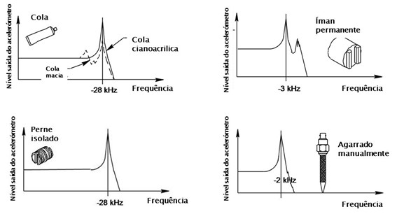
Frequency Response Effects of Montage of the piezoeletric accelerometers
O Ski Slope – Connection and stabilization time of piezoelectric accelerometers
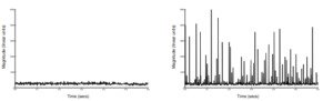
When power is supplied to an accelerometer, There is a turn-on time for the amplifier circuit to energize and reach a stable bias voltage before vibration measurement can begin. Activation time is identified as the time required to reach or normalize the +/- 10% of the bias voltage. Allowing the accelerometer to stabilize around the bias voltage will prevent sky slope in the FFT spectrum.

The “sky slope” manifests itself in the frequency spectrum in the form of spectral components of very low frequency and very high amplitude. The “sky slope” which consists of the result of the frequency analysis of the DC component of the unstabilized signal, can cause serious problems, to those who measure vibrations.
Correct way to assemble piezoeletric accelerometers in data collection
When collecting data with portable equipment, the accelerometer is powered when the data collector is turned on and the accelerometer will remain on until the data collector is turned off at the end of the collection process. If a portable accelerometer is being mounted with a magnet (or assembled by other temporary means), It takes some time for the amplifier circuit to stabilize after the assembly shock. This is known as settling time. The time it takes for the amplifier circuit to stabilize after temporary mounting is very dependent on the mounting process. If the accelerometer is rigidly mounted to the machine, allowing the magnet to impact the mounting surface, the shock of mounting will saturate the amplifier and it will be necessary. a long stabilization time. If the magnetic mount mounts smoothly to the mounting surface, with little or no shock to the accelerometer, stabilization time will be minimal. It is always preferable, in portable data collection, mount the accelerometer as smoothly as possible, to avoid any sensor shock or amplifier saturation. This allows the measurement process to start faster, save time between measurements and avoid “sky slope” in the FFT spectrum.
Spectral noise level of piezoeletric accelerometers
Each accelerometer has a noise level (“noise floor”) and the amplitude of this noise is typically measured in 10, 100 e 1000 Hz in units of µV divided by the square root of the frequency, which is equivalent to the square root of the PSD (Power spectral density). Dividing the measured µV/√Hz value by the accelerometer sensitivity yields a µg value / √Hz. For example:
• Spectral noise measured at 10 Hz = 1,4 µV/√Hz
• With sensitivity of 100mV/g, Spectral noise at 10Hz = 14 µg/√Hz
• Now we can calculate the noise amplitude at 10Hz as 14 µg/√10 = 4,43 µg
4,43 µg would be the amplitude of the noise in 10 Hz. To take a measurement above the noise level, with acceptable noise tolerance, o SNR (Signal Relationship / Noise) must be at least 10 for 1, that is, the vibration amplitude must be at least 44,3 µg in the example above. The low spectral noise will allow a good measurement to be made and keep the signals of interest well above the accelerometer noise level.
dynamic range of the piezoeletric accelerometers
Range of levels the accelerometer can measure, which can be expressed in different ways
The full scale of IEPE sensors is typically ±5 Volts output signal